
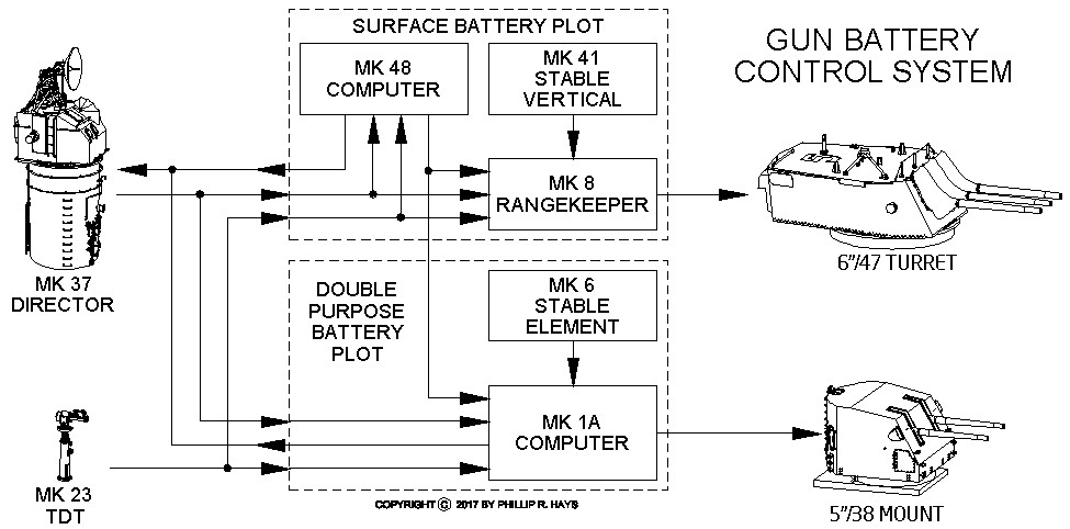
The ship's gun battery of three 6"/47 guns and two 5"/38 guns was controlled from Gun Plot. There were two separate plotting rooms, one for the Surface Battery 6"/47 guns, and one for the Double Purpose Battery (surface and anti-air) 5"/38 guns. Target information was passed from the Combat Information Center (CIC) by voice communications for indirect fire, or when CIC assigned a target to the Mk 37 Gun Director for direct fire. The Director could be used to control either gun battery. Gun plot would recommended courses to the Bridge for the ship to steer to "unmask" the guns - so the ship's superstructure would not be in the way of engaging the target.
Surface Battery Plot
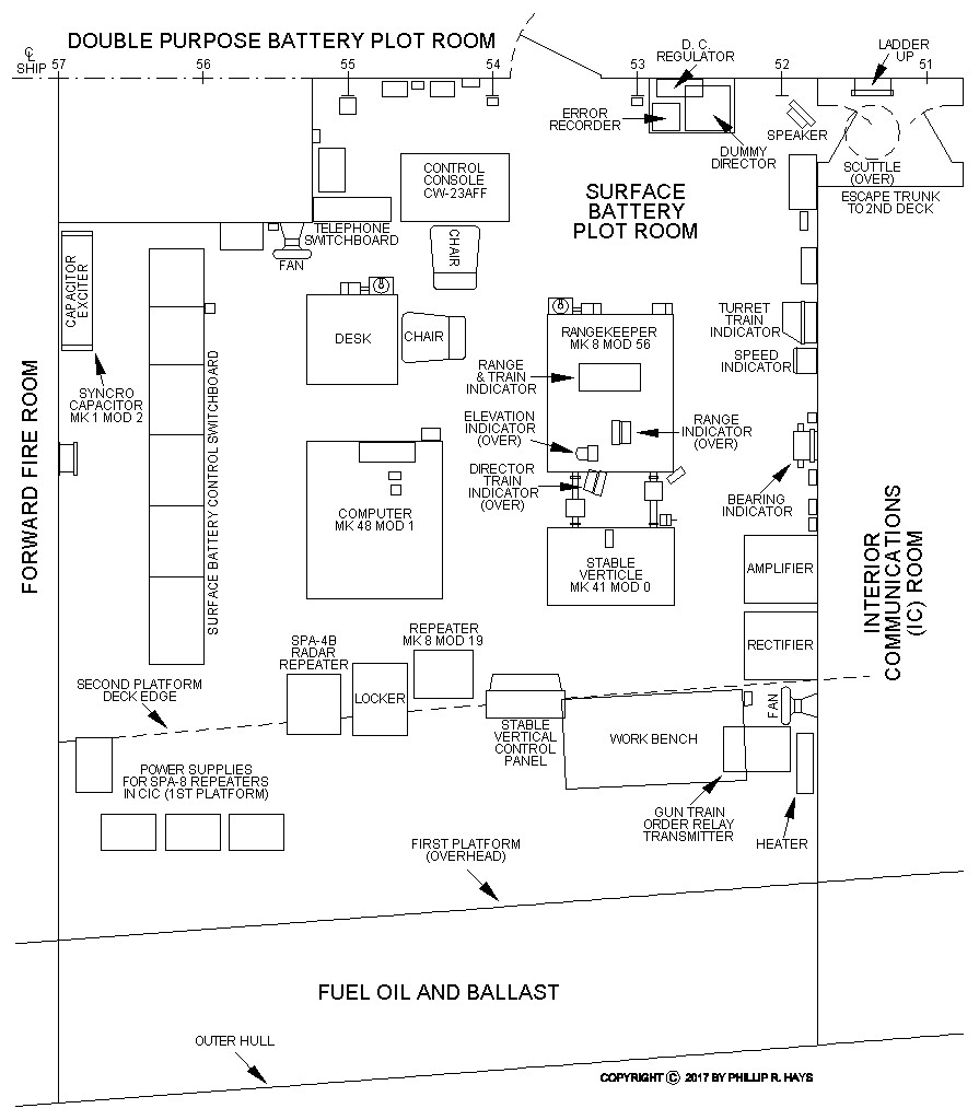
The Surface Battery Plot Room controlled gunfire from the triple 6"/47 turret. The room was located on the starboard side of the 2nd Platform just forward of the Forward Fire Room (boiler room). Access to Surface Plot was through the Double Purpose Plot Room on the port side of the 2nd Platform. The 2nd Platform was the lowest deck in the ship, about 17 feet below the water line. Below this were fuel oil tanks and ballast. Portable (removable) plates in the deck allowed access into the tanks below. The fuel oil tanks extended up the side of the ship outboard, creating a double hull for protection from torpedoes and mines. An Escape Trunk forward on the ship center line provided an emergency escape passage up to the 2nd Deck for Surface Plot and the Interior Communications Room just forward of Surface Plot.
The function of the equipment and crew in Surface Plot was to calculate the bearing and elevation of the 6"/47 guns so projectiles fired from the guns would hit their targets. Direct and indirect fire was controlled there, and the 6" guns were fired from Surface Plot for indirect fire missions. The Mk 48 Computer in Surface Plot could also be used to calculate indirect fire solutions for the Mk 1A Computer and the Double Purpose Battery 5"/38 guns. Actually getting the bullets to the bullseye involved many pieces of equipment and a lot of calculations.
Mk 48 Computer
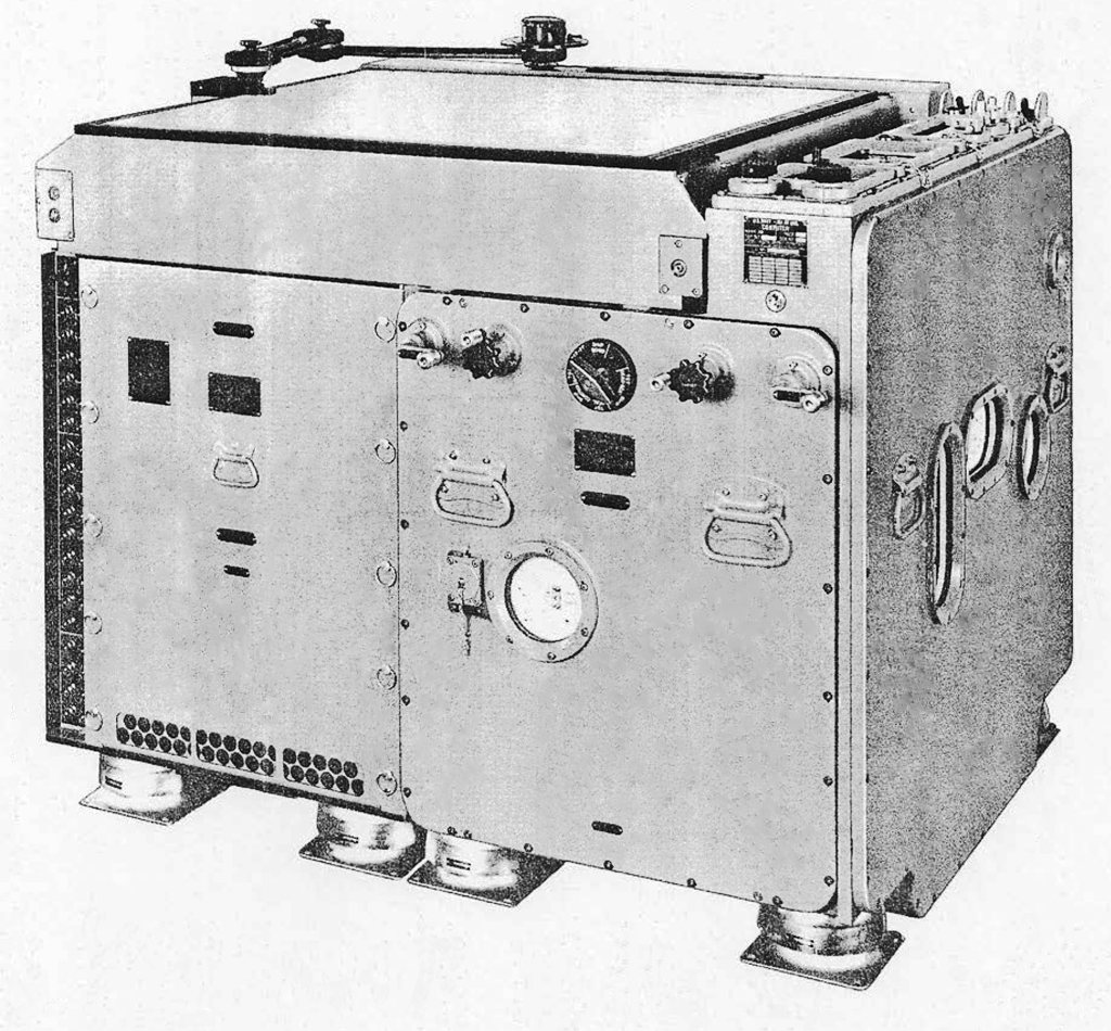
The Mk 48 electro-mechanical analog computer calculated gunfire solutions for indirect fire missions where the target was not directly visible from the ship. The Mk 48 supplied target range and bearing to the Mk 8 Rangekeeper in Surface Plot to control the 6"/47 guns, and to the Mk 1A Computer in Double Purpose Battery Plot to control the 5"/38 guns. The Computer mechanism consisted of many mechanical integrators, cams, differentials, resolvers and multipliers with vacuum tube signal buffers and amplifiers crammed into a box 54 inches long by 47 inches wide by 42 inches high.
The computer used three known points to calculate the solution. First was a visible reference point that was tracked by the Mk 37 director, providing range, bearing and elevation information to the reference relative to the ship. The second point was the geographical position of the ship. The third point was the geographical location of the target. An indicator panel on the top right side of the computer displayed ship, reference and target information. Hand cranks and knobs on the sides were used to enter data and manually position the tracking mechanism.
The top of the computer was a plotting mechanism similar to a Dead Reckoning Tracer. A nautical chart (map) of the region around the target was placed on the plotter and aligned with its coordinate system. The operators then entered the chart scale into the Computer to match Computer calculations to chart distances. The plotter mechanism projected a spot of light upward through the chart - the Index Light. A Parallel Motion Protractor mechanism on the top allowed the operators to measure bearings and ranges on the chart.
The Computer operators used knobs to set the reference point height and target height to values read off the chart. They set a Mode Switch to "Reference Point Select" and then used Reference X and Y hand cranks to move the Index Light to the reference point on the chart. This entered the geographic coordinates of the reference point. Next they set the Mode Switch to "Target Select" and used the Target X and Y hand cranks to move the Index Light to the target position on the chart. This gave the computer the geographic coordinates of the target. These reference and target positions were normally not changed after they were set unless a new target was selected. The Index Light normally illuminated the target position.
The computer then positioned the Mk 37 Director to aim at the reference point. The Director crew adjusted the Director to aim precisely at the reference and maintained continual track of the reference. This gave the Computer constant updates on the ship's position relative to the reference. The Computer used the relative range and bearing to the reference point to determine the ship's geographic coordinates, and therefore the relative bearing and range to the target. If the Director range and bearing information updates failed, the Computer operators could enter updates to the range and bearing manually using information supplied by the navigation watch. The computer could also use information from the ship's gyro compasses to determine the ship's heading, and speed information from the pitometer log, and update the ship's position continually. In this respect it acted the same as the Dead Reckoning Tracers on the Bridge and in CIC, updating the ship's position on the chart as it maneuvered, but this was not as accurate as using range and bearing to a reference point. Additional Computer inputs allowed entering corrections manually if automatic updating of the ship's position failed because of a gyro or pit log malfunction, using positions calculated by the ship's navigation watch on the Bridge and in CIC.
The Computer continually calculated the target position relative to the ship's position and sent this information to the Mk 8 Rangekeeper or the Mk 1A Computer in the Dual Purpose Gun Plot Room. Using information from the Spotter the operators could adjust the target position using East-West and North-South spot knobs. They could also use the Target X and Y hand cranks to move the target position around the target area on the chart to cause the guns to fire at points around the target point to saturate the area.
Periodically the operators set the Mode Switch to "Ship" and the Computer would move the Index Light to the ship's position on the chart. This position and time were marked on the chart to keep a record of the ship's movements. They could use the Parallel Motion Protractor to plot the theoretical position of the ship from one of these actual positions using the gyro compass courses and pitometer log speeds. But this gave only the ship's movement through the water, not taking into account any movement of the water and influences winds may have on the ship's motion. By comparing the theoretical position with the actual position they could determine the set and drift of local currents. Drift is the speed of the current and set is the direction of the current. These factors could introduce errors into the ship's position if the Mk 37 Director did not provide reference position information, and that would cause errors in firing on the target. The set and drift were recorded and could be entered into the Computer as north-south and east-west corrections to the ships position if necessary.
Mk 8 Rangekeeper
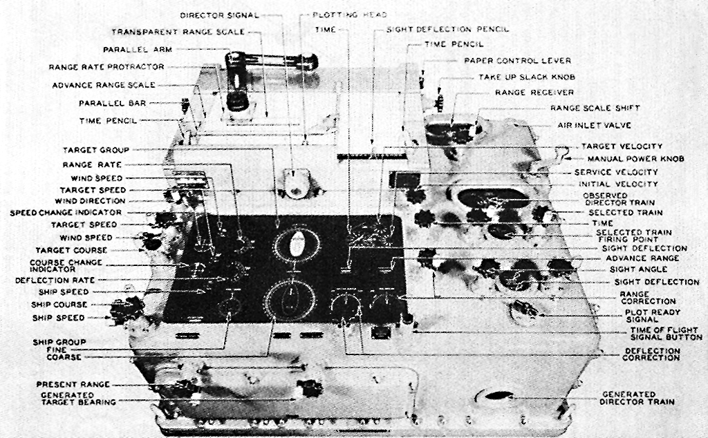
The Mk 8 Rangekeeper actually aimed the 6"/47 guns. It calculated the bearing and elevation for the 6"/47 turret and guns continuously. It was another electro-mechanical analog computer, and was the predecessor of the Mk 1 Computer used in the Dual Purpose Battery Plot to do the same thing for the 5"38 mount and guns. For direct fire missions the Rangekeeper used range, bearing and elevation information from the Mk 37 Director. With indirect fire missions it received range, bearing and elevation information from the Mk 48 Computer. It received coarse and speed information from the ships gyro compass and pitometer log, corrections for roll, pitch and yaw from the Mk 41 Stable Vertical, and wind speed from the anemometers. The gun plot crew entered information about the type of projectiles and powder being fired.
From this information the Rangekeeper calculated the relative motion between the ship and the target, and predicted the future relative position of the target when the projectiles would arrive. It corrected for the Earth's curvature, wind speed, the effects of gravity, the spin of the projectile and the Coriolis effect due to the Earth's rotation. Finally, the Rangekeeper corrected parallax errors caused by the distance between the turret and the gun Director. They were separated by about 140 feet along the length of the ship and about 56 feet vertically. Without correction for these distances shells would miss the target by more than 100 feet.
Mk 41 Stable Vertical
The Stable Vertical was a gyroscope that determined true vertical, relative to the center of the Earth, while the ship was rolling, pitching and yawing. The firing triggers for the gun battery were located on the Stable Vertical. When all of the elements of the gunfire control system had calculated the gun fire solution a crewman fired the guns from the Stable Vertical.
Surface Battery Control Switchboard
The fire control switchboard allowed the Surface Plot crew to select the sources and outputs for the gunfire control system. Either the 6"/47 turret or 5"/38 mount could be controlled from Surface Plot. The Mk 37 Director, one of the two Target Designation Transmitters or the Mk 48 Computer could be selected for bearing and range information for the target. In addition, critical wiring circuits were duplicated throughout the ship, usually one circuit on the port side and another on the starboard. If one circuit was damaged the switchboard operator would select the parallel circuit to ensure parts of the gun battery remained connected to each other. The Double Purpose Battery Plot Room had a similar Double Purpose Battery Control Switchboard.
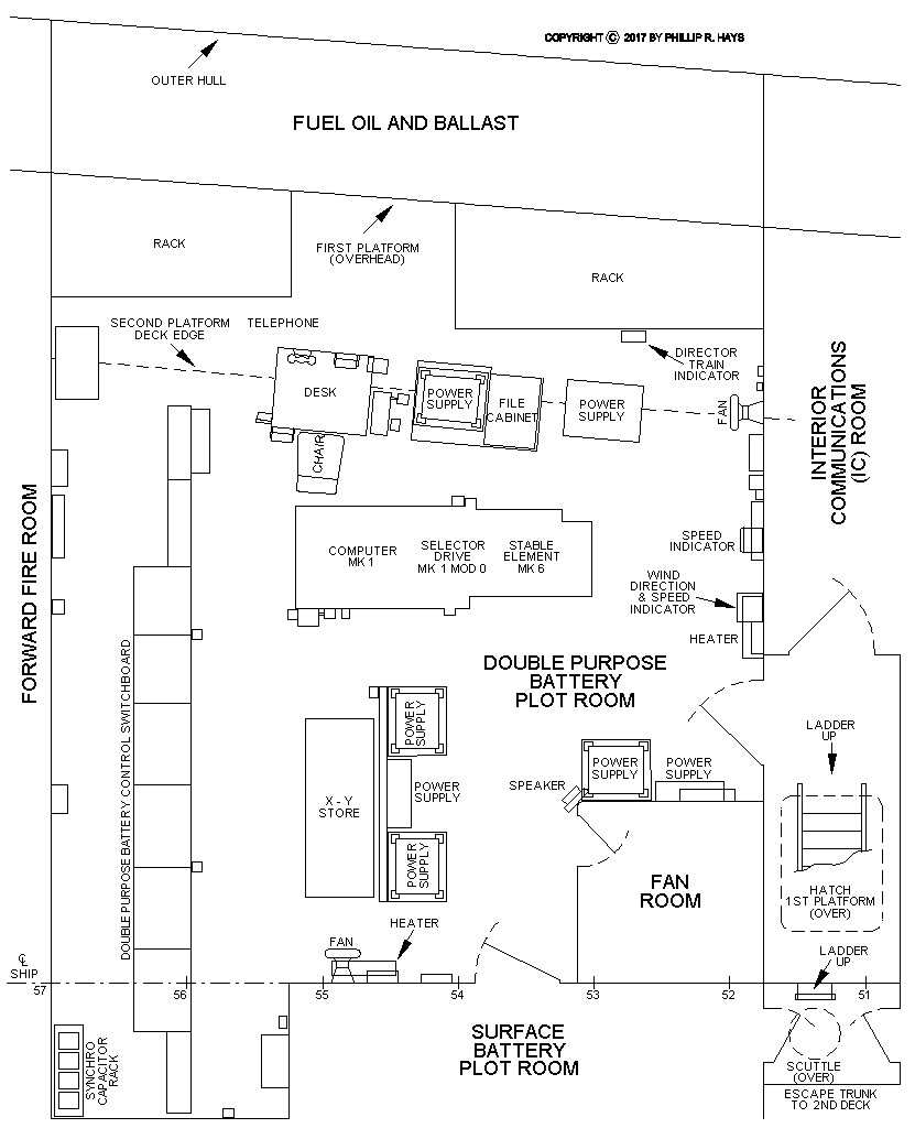
Double Purpose Battery Plot
The Double Purpose Battery Plot Room controlled gunfire from the dual 5"/38 gun mount. The room was on the port side of the 2nd Platform forward of the Forward Fire Room. A door opened to starboard into the Surface Battery Plot Room. The main access to both plot rooms was a door that opened from the Double Purpose Plot Room to a ladder descending from the 1st Platform above. Like the Surface Battery Plot Room, fuel tanks and ballast spaces were below and outside the Double Purpose plot room, and portable plates in the deck allowed access to the fuel and ballast spaces below.
The job of the personnel and equipment in the Double Purpose plot room was to aim the 5"/38 guns so they could hit their targets. The procedure was almost the same as with the Surface Plot control of the 6"/47 guns, except that the Double Purpose guns could also engage airborne targets. For indirect fire the Mk 48 Computer in Surface Plot fed target bearing, range and elevation information to the Mk 1A Computer in Double Purpose plot. For direct fire against land, sea and air targets the Mk 37 Director supplied target information to the Mk 1A Computer.
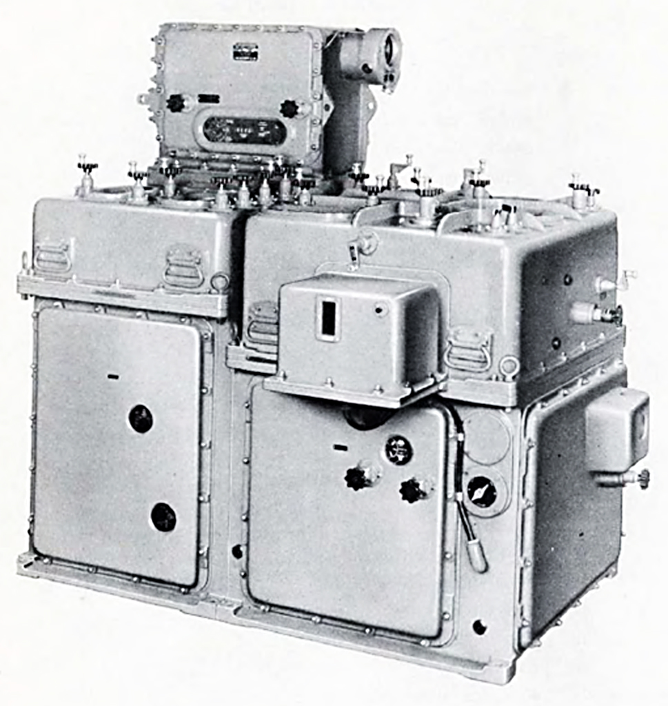
Mk 1A Computer
The Mk 1A Computer was an improvement of the Mk 8 Rangekeeper, with the additional ability to track airborne targets that were changing bearing, range and elevation. In theory the Computer could track airborne targets moving up to 1200 knots. The Computer did all of the calculations to aim the 5"/38 mount and guns, and did it faster than the Mk 8 (important for engaging high speed aircraft and missiles). It received bearing, range and elevation information from the Mk 37 Director, which it was designed to work with as part of the Mk 37 Gun Fire Control System. As the Director information changed the Computer made running calculations of the bearing, range and elevation to the target and eventually derived a solution for the target's actual course and speed. While doing the calculations it controlled the Director to keep it on target. With the targets course and speed known the Computer calculated gun lead angles and fuze settings for time delay fuzes. Then the gun battery could open fire.
The Computer also used wind direction and speed, the ship's course and speed and ship motion information to correct the firing solution. It used information about the type of projectile and powder being used and specific gun ballistic information. The parallax offset between the Director position and the gun mount was also included in the calculations. From all of this information it aimed the guns and calculated the flight time of the projectile to the target. The flight time was used to send fuze settings to the automatic fuze setters in the gun mounts. This caused projectiles with Mechanical Time Fuzes to detonate close to the target if they did not actually hit the target, and that increased the probability of inflicting damage with a near miss.
During World War II the radio proximity "VT" fuze was developed that would detonate the shell if it passed close to the target, reducing the importance of timed fuze settings. But the timed fuzes were still used, sometimes mixed with the VT fuzes when firing at aircraft to provide air bursts for spotting even if the rounds missed the target. The timed fuze was also used against troop concentrations in the open to cause shells to explode above the ground and scatter shrapnel over an area.
The Computer was not an electronic calculator. All of these calculations were made with dozens of mechanical gears, cams, disk-ball-roller integrators, non linear cams, differentials, resolvers and multipliers powered by constant speed motors. It was a metal box 62 inches long, 38 inches wide and 45 inches high jammed full of moving mechanical parts.
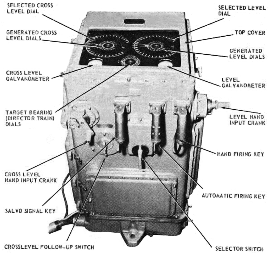
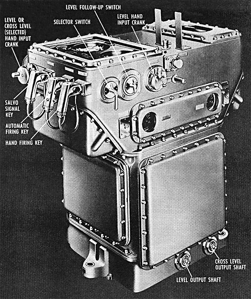
Mk 6 Stable Element
The Stable Element was a gyroscope that functioned like the Mk 41 Stable Vertical to determine true vertical relative to the Earths center. It served two functions. First it sent signals to the Mk 37 Director to cause the optical range finder and Mk 25 radar antenna to rotate and remain horizontal with respect to the horizon as the ship (and Director) rolled, pitched and yawed. The second function was to provide similar roll, pitch and yaw correction information to the Mk 1A computer. For direct fire missions the guns were fired from the Mk 37 Director. For indirect fire missions the 5"/38 guns were fired from the Stable Element.
References
1. OP 1063, Stable Element Mk 6 and Mods, Department of the Navy Bureau of Ordnance, January 1944.
2. OP 1719, Gun Fire Control System Mk 37 Operating Instructions, Navy Department Bureau of Ordnance, 21 April 1949.
3. OP 2074, Computer Mk 48 Mod 1 Description, Operation, Installation and Maintenance, Department of the Navy Bureau of Ordnance, 29 September 1956.
4. BUPERS 10798-A, Naval Ordnance and Gunnery, Volume 2, Chapter 19, Surface Fire Control Problems, Department of Ordnance and Gunnery United States Naval Academy, 1958.